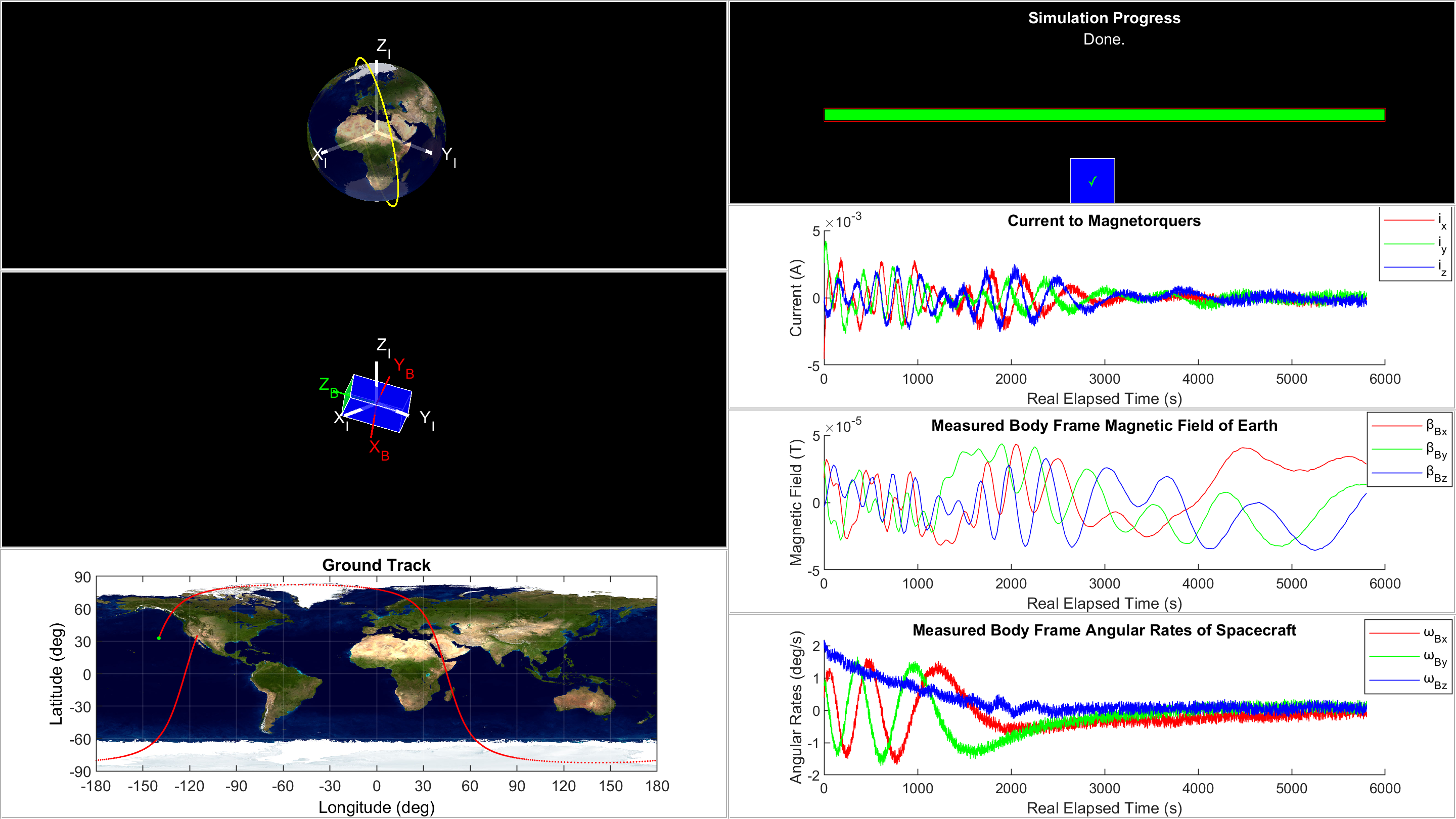
When a satellite such as a CubeSat (a small 10 cm x 10 cm x 10 cm spacecraft) is released from its deployer, it tumbles about all axes and must be detumbled before mission operations can take place. Detumbling is the process of slowing the body angular rates of a satellite down until its attitude (angular orientation) is stabilized in orbit. After a satellite is detumbled, the on-board attitude determination and control system (ADCS) can use deterministic methods to acquire initial attitude measurements with respect to the inertial reference frame (the Earth-centered inertial (ECI) frame), and recursive methods to perform tasks like nadir-pointing and attitude maintenance. Written in MATLAB, this CubeSat Detumbling Simulator (originally developed for UCI CubeSat) allows the user to simulate the detumbling phase of a LEO CubeSat (with at least a 3-axis magnetorquer set, a magnetometer, and a gyroscope) using a B-dot controller and low pass filters (for sensor noise attenuation) in a closed-loop feedback process.
Hardware
- Minimum RAM: 8 GB
- Recommended: Dedicated Graphics Card
Software
- MATLAB (Ideally R2020b or later)
- MATLAB Aerospace Toolbox
Download and unzip the files. Open Main.m in MATLAB. In the "Main Parameters" section, initialize the program by assigning values to each of the parameters, making sure to stay within the allowable range for each parameter. Run Main.m.
If the simCalcltnMdfier parameter is set to 'Real-Time', a GUI window will pop up and will update in real-time as the simulation progresses. While the real-time simulation is
running, calculation can be paused/continued by toggling the pause/play button under the simulation progress bar.
If the simCalcltnMdfier parameter is set to 'Pre-Calculate', the program will run the simulation without real-time updates to the GUI. After the pre-calculations finish,
the GUI window will appear showing the final output. Pre-calculation is significantly faster and potentially a bit more accurate as sampling periods are pre-determined and
MATLAB's clock and etime functions are not needed for timing.
Once the simulation finishes, a summary of run details will be outputted in the MATLAB Command Window. The code may be edited as desired for customized simulation outputs.
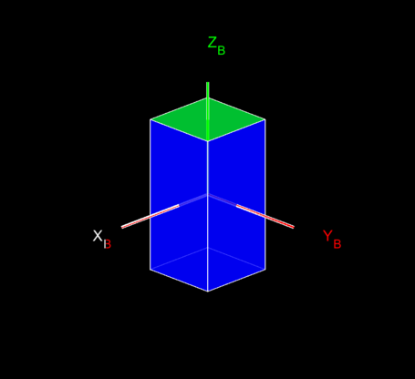
- The default orientation of the CubeSat looks something like the image below. The red/green reference frame is the CubeSat's body frame and the white reference frame is the
ECI frame. The
initYawAngl_spcrft(about body Z),initPtchAngl_spcrft(about body Y), andinitRollAngl_spcrft(about body X) parameters (in that order) define the intrinsic body frame rotation sequence that represents how the CubeSat will initially be oriented relative to the ECI frame when ejected from the deployer. Note that an intrinsic rotation defined by yaw-pitch-roll about body frame axes is the same as an extrinsic rotation defined by roll-pitch-yaw about inertial frame axes.
- The
viewAzmthandviewElvtnparameters are passed into MATLAB's view command in the code to set the "camera line of sight" for the orbit plot and the spacecraft plot. In other words, these parameters change the angle at which the user sees the ECI frame in these two plots.
- The orbit model is simplified to only support circular orbits (eccentricity = 0) between 200 km and 850 km altitude with nonzero time rates of change for argument of periapsis (AOP) and right ascension of the ascending node (RAAN) to model the J2 pertubation effect, and zero rates of change for all other Keplerian elements.
- Disturbance forces and torques on the CubeSat were neglected so that the simplified analytical solution to the gravitational 2-body dynamics equations could be used.
- The only actuators used in the detumbling algorithm are the 3 magnetorquers and the only sensors used are the magnetometer and the gyroscope (often packaged together in an inertial measurement unit (IMU)). Obviously, due to the nature of this being a non-HIL simulation, the sensor "measurements" are just direct functions of the simulator models with the addition of white Gaussian noise and constant bias.
- Euler's method (RK-1) is used for iterative computations as opposed to something like Runge-Kutta 4 (RK-4) to prioritize computational speed over accuracy. The user may replace RK-1 computations with RK-4 (or other iterative methods) if higher accuracy is desired.
[1] Curtis, Howard D, Orbital Mechanics for Engineering Students, 3rd ed. Embry-Riddle Aeronautical University, Daytona Beach, Florida: Butterworth-Heinemann Elsevier Ltd., 2014.
[2] Montalvo, Carlos. "ADCS for LEO Satellites." YouTube. https://www.youtube.com/playlist?list=PL_D7_GvGz-v3mDQ9iR-cfjXsQf4DeR1_H.
[3] Sanderson, Grant [3Blue1Brown] and Ben Eater. "Visualizing Quaternions: An explorable video series." eater.net. https://eater.net/quaternions/.
[4] Armesto, Leopoldo. "Quaternions: Robotic Systems." YouTube. https://www.youtube.com/watch?v=0FbDyWXemLw&t=309s.


